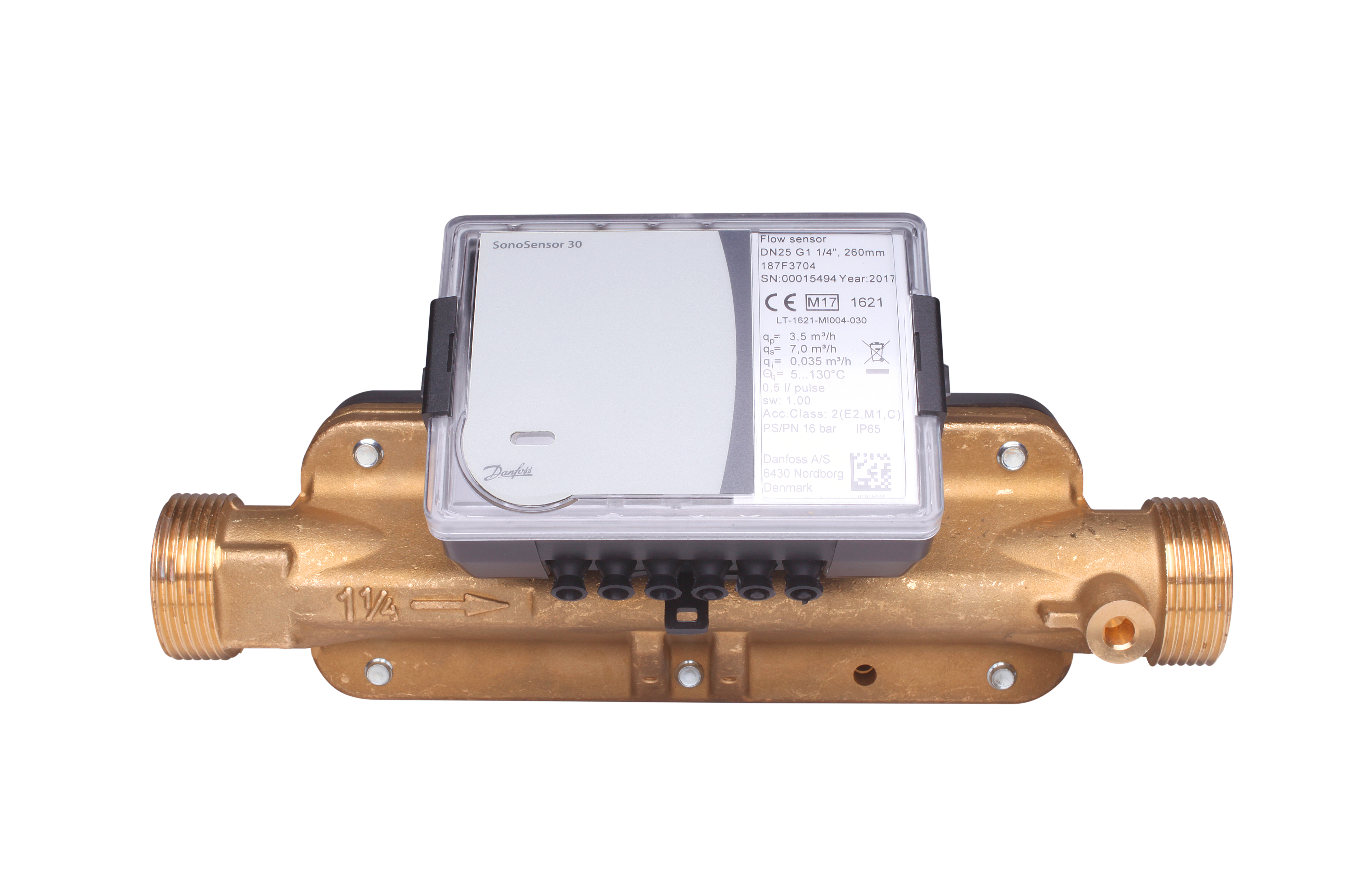
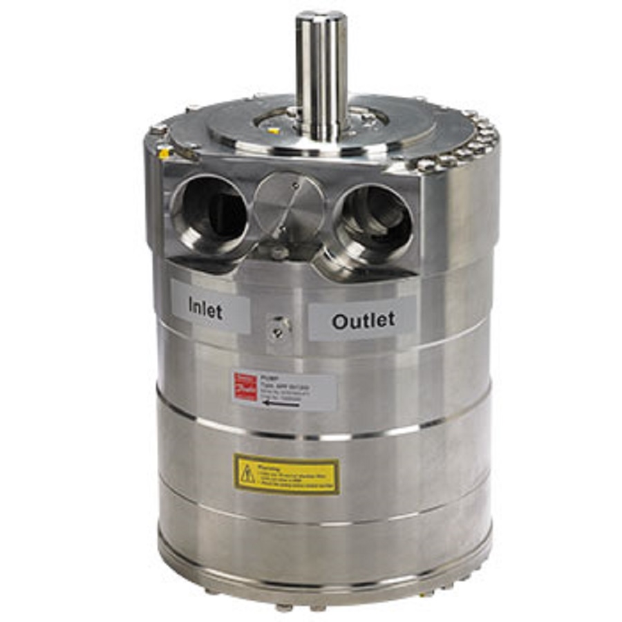
Basic Elements
- Danfoss Flow Meter User Manual Transfer Switch
- Danfoss Flow Meter User Manual Diagram
- Danfoss
- Danfoss Flow Meter User Manual Download
- Danfoss Flow Meter User Manual Pdf
- Summary of Contents for Danfoss PFM 100 Page 1 Flow and pressure can be displayed in various units, which you can choose from in the menu. The PFM 100 can communicate with you in one of 10 possible lan- guages. Please note that the pressure unit must not be exposed to sub- zero temperatures.
- 5th draft – SW 1.91 (User manual + parameter description) 0.99 16th of February 2015 6th draft – SW 1.92 0.992 27th of March 2015 7th draft – SW 1.93 0.995 10th of July 2015 8th draft – SW 1.93 0.999 28th of October 2015 Updated for 1.95 Software release 1.1 20th of November 2015 Updated according to internal review (#1347) 1.11.
- Danfoss only vouches for the correctness of the English version of this declaration. In the event of the declaration being translated into any other language, the translator concerned shall be liable for the correctness of the translation. ID No: DPD01856 Revision No: A Page 1of 1 Danfoss A/S DK-6430 Nordborg Denmark CVR nr.: 20 16 57 15.
- With an oil flow to the motor sufficient to ensure even revolution with a warm motor. Measure the following duty cycles: User Manual Test Instruction for Orbital Motors with Speed Sensor Motor with speed sensor 11043901. Rev BA. Mar 2014 5.
Just like other flowmeters, differential pressure flowmeters consist of two elements. They are:
A primary element: This element causes a change in kinetic energy which results in the differential pressure in the pipe. The unit must be suitably matched to the
- pipe size,
- flow conditions, and
- the liquid’s properties
Besides, the measurement accuracy of the element must be fine over a practical range.
A secondary element: The secondary element measures the differential pressure created by primary element and gives the signal or read-out which is in turn transformed to the actual flow value.
The conditions require meters with a robust construction and fulfilling high demand requirements on e.g. Temperature and pressure. These meters cover sizes from DN15 up to DN100 with flow rates from 0.6 up to 60 m3/h and are available in pressure range PN16 and PN25.
Types of Differential Pressure Flowmeters
Most widely used differential pressure flowmeters are:
- Orifice Plates
- Flow Nozzles
- Venturi Tubes
- Variable Area flowmeters, i.e. Rotameters
Accuracy & Rangeability
Performance of a head-type flowmeter installation is a function of the
- precision of the flow element and
- the accuracy of the d/p cell
On average, flow element precision is expressed in percentage of actual reading terms, whereas d/p cell accuracy is stated as a percentage of calibrated span. A d/p cell typically provides accuracy of ±0.2% of the calibrated span. With no detrimental effect on accuracy, rangeability of a flowmeter can be extra enhanced by employing several d/p flowmeters in parallel runs.
Errors and Noise
In case of compressible fluids, the ratio of differential pressure divided by upstream pressure should not exceed 0.25 for reduction of error and correction of density. Metering errors caused due to wrong installation of the primary element can become considerable i.e. up to 10%. Following are the possible causes of these errors:

- the condition of the mating pipe sections
- insufficient straight pipe runs
- pressure tap and lead line design errors
In turbulent flow conditions, not more than 10% of the d/p signal could possibly be noise produced by disturbances from valves and fittings. These disturbances can be both up- and downstream of the element, and by the element itself. To sort out this noise, a damping is provided in d/p cells which prove to be adequate for majority of the applications. Rigorous noise can be diminished by applying two or more pressure taps connected in parallel on both sides of the d/p cell.
Sources
OmegaTech
Engineering Toolbox
Omega.literature
Here you will find our documentation such as data sheets and operating manuals for our measuring instruments. If you do not find the document, approval or certificate you are looking for, please contact us, we look forward to hearing from you (info@metra-emt.de)!
Your team from METRA Energie-Messtechnik GmbH
Brochures
Product data sheets

| Measurement system “oriflow” with compact orifice |
| Measurement system “autarkon” with compact orifice – EWZ 120.1 & EWZ 127.1 |
| Measurement system “autarkon” with standardized differential pressure devices – EWZ 140.1/147.1 |
| Measurement system “autarkon” with venturi tube 150.1/157.1 Steam / Gas |
| Measurement system “autarkon” with venturi tube – 150.1/157.1 Liquids |
| Measurement system “autarkon” with cross probe – EWZ 211.7 |
| Measurement System “autarkon” with cross probe – EWZ 311.7 |
| Ultra sonic meter for heat / cooling applications – EWZ 817 |
| Ultra sonic meter for heat / cooling applications – EWZ 817G |
| Ultra sonic meter for heat / cooling applications – EWZ 817T |
| Ultra sonic meter for heat / cooling applications – EWZ 837 |
| Magnetic inductive meters for cooling applications – EWZ 617 |
| Magnetic inductive meters for cooling applications – EWZ 617 calibrated |
| Vortex Meter – VTX3 |
| Flow and Energy Calculator – ERW 700 |
| Temperature sensor |
Operating Manuals
| Measurement system “oriflow” with compact orifice |
| Measurement system “autarkon” with compact orifice – EWZ 120.1 & EWZ 127.1 |
| Measurement system “autarkon” with standardized differential pressure divices – EWZ 140.1/147.1 |
| Flow and energy calculator ERW 700 |
| Flow and energy calculator ERW 700, “M-Bus Extension” |
| Flow and energy calculator ERW 700, “Profibus Extension” |
| Flow and energy calculator ERW 700, “RS 485 Extension” |
| Flow and energy calculator ERW 700A |
| Flow and energy calculator ERW 700(A) “Modbus Extension” |
| Measurement system “autarkon” with cross probe – EWZ 211.7 |
| Measurement system “autarkon” with cross probe – EWZ 311.7 |
| Ultra sonic meter for heat / cooling applications EWZ 817 / EWZ 837 |
| Magnetic inductive meters for cooling applications – EWZ 617 |
| Vortex Meter – VTX3 |
| Vortex Mester VTX3 additional Manual Ex-protection |
| Temperature sensor |
Danfoss Flow Meter User Manual Transfer Switch

APPLICATION EXAMPLE
| Steam Measurement by mean of a ISA 1932 Nozzle |
| Standard volume flow measurement Venturi tube |
MID
Danfoss Flow Meter User Manual Diagram
| Messsystem “autarkon” mit Kreuzsonde |
| Durchfluss- und Energierechner – Wärme |
| Durchfluss- und Energierechner – Kälte |
Pressure Equipment Directive
| EC Type Examination Certificate Module H Vortex Meter VTX3 |
EC Type Examination Ex- Approvals
Danfoss
| EU Type Examination Certificate Vortex Meter VTX3 KIWA 18 ATEX 0041 X |